

Dynamic Process Simulation with Modelica -Simulating PtX Processes Dynamically
Is your current process simulation software too inflexible? Our Modelica library for process engineering allows you to design and optimize new Power-to-X processes.
Our simulation experts support you with the expertise from over 250 customer projects.

Selected customers


"The process engineering of the future is dynamic! The trends of decarbonization, electrification, and renewable energies require new processes, often in dynamic operation. To unlock their potential, process simulations based on flexible open software solutions like the Modelica library PSL are a decisive advantage."

Prof. Dr.-Ing. André Bardow
Energy and Process Systems Engineering, ETH Zurich
“The world needs efficient carbon capture processes! Developing energy efficient and safe solutions require professional and reliable simulation tools for process improvements and adaptations to customer needs. Ocean GeoLoop takes advantage of the possibilities available in TLK Energy's process systems library.”

Samuel Krämer
Process Engineer
Ocean GeoLoop
Dynamic Simulation of PtX Processes – Software and Consulting in One Package.
Expertise from 250+ successful customer projects
A team of 20 simulation experts with several years of experience is at your side, bringing the expertise from many successful customer projects.


Modelica library optimized for PtX processes
Our PSL (Process Systems Library) is a Modelica library for process engineering.
- In-house developed core for dynamic two-phase flows (encrypted)
- All other equations are open
- Easily customizable and expandable
- Base PSL open source available (coming soon)
No dependency on a software provider
We are not ASPEN. As a small specialized provider, we do not want or can offer an all-encompassing software solution. Instead, we believe in the interplay of specialized solutions. Therefore, we rely on:
- Open standards (Modelica, FMI)
- Well-documented APIs
- Partnerships with universities and other companies

Your new opportunities in dynamic simulation of PtX processes

Open Code
The open code makes it easy for you to look at and understand the equations.

Modular structure
Thanks to the modular, object-oriented structure, you can flexibly reuse models.

Open interfaces
Combine our models with models from other libraries, such as our TIL Library.

Export possible
Export models as FMUs to compute them anywhere at no extra cost.
This is how we start collaborating with our clients.
1
Analysis
What questions do you have? Are you already using process simulation? Where do current tools encounter limitations?
2
Agile Pilot Project
We create custom models based on the PSL library. In regular meetings, we discuss interim results and next steps. You will receive the created models as source code and a 6-month PSL trial license.
3
Flexible Partnership
You use the PSL Modelica library for the dynamic simulation of your PtX processes. We are here to provide our expertise whenever you need it.
Use case examples
System
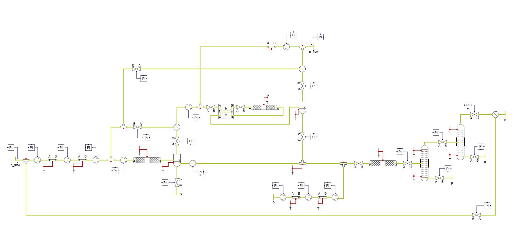
High-temperature Fischer-Tropsch synthesis (HT-FT) is a Power-to-Liquid (PtL) process to produce sustainable aviation fuels (Sustainable Aviation Fuel, SAF). The goal of the process is to generate synthetic hydrocarbons from renewably obtained hydrogen (H2) and carbon dioxide (CO2) to close the carbon cycle in aviation as far as possible.
The process is divided into several stages: In the first step, H2 and CO2 react in an HT-FT reactor to form a mixture of water as well as various olefins and paraffins. Since long-chain molecules are required for SAFs, an oligomerization reactor follows, which links the short-chain olefins into long-chain ones. In the subsequent hydrotreatment, remaining unsaturated compounds are saturated (olefins become paraffins).
The conclusion is formed by two distillation columns, in which the end product SAF is separated from by-products such as synthetic gasoline.
Simulation
A special feature of the developed model lies in the mapping of the reaction kinetics: Complex kinetic models were implemented that go beyond simple, fixed conversion rates. For the oligomerization reactor, for example, a detailed reaction network based on elementary reactions was generated using the open-source software RMG (Reaction Mechanism Generator).
The focus of the simulation analysis is on the chemical composition of the end products, the flexibility of the model, and the part-load behavior. Therefore, among other things, the model behavior during a reduction of the molar feed stream by 50% was analyzed.
Results
The following figure shows the molar outputstreams of SAF and gasoline at the respective columns, divided into individual paraffins (C2H6 to C15H32). For SAF, longer chains in the range of C8H18 to C15H32 are present in relevant proportions; for the gasoline (Gasoline), shorter chains in the range of C5H12 to C7H16.
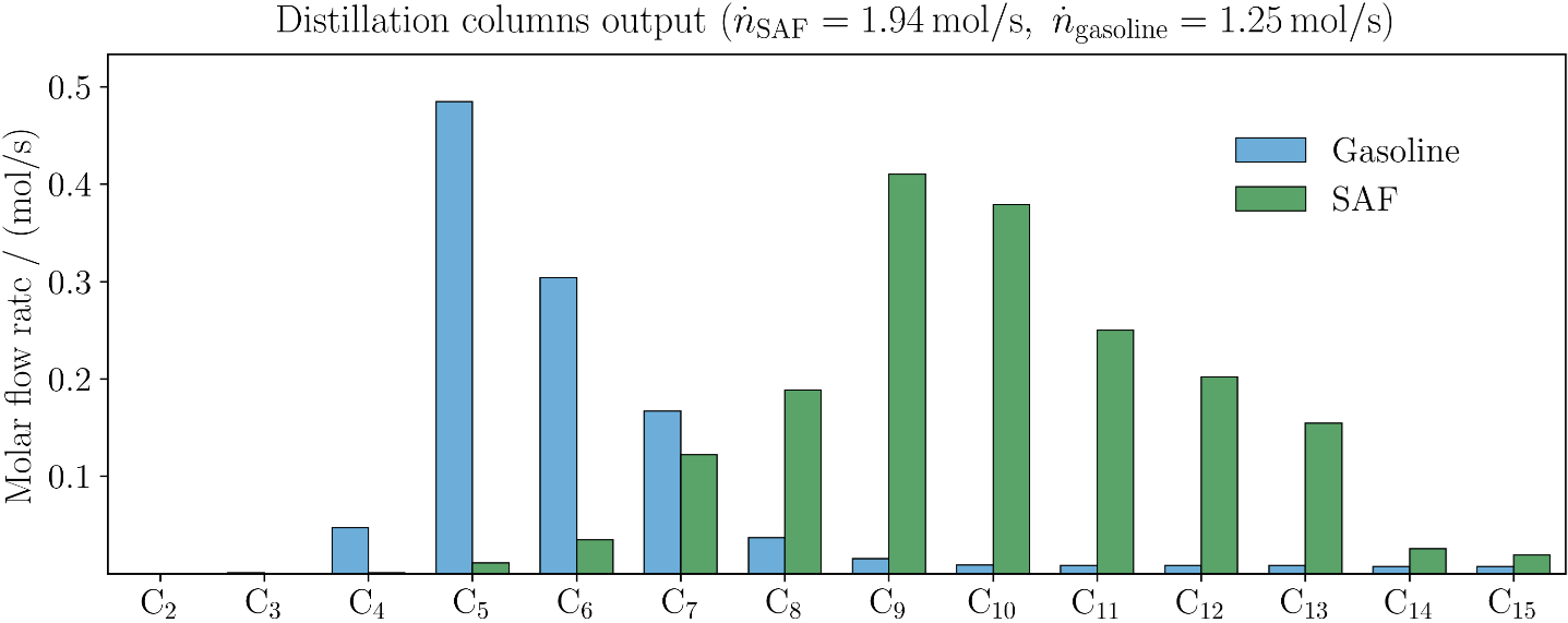
Furthermore, the simulation shows that the model at the reference point delivers an SAF mass flow of 0.28 kg/s at a process efficiency of about 45%. With a reduction of the input stream by 50%, SAF production drops disproportionately by 62%, which is attributable to lower utilization and a shift in product fractions. Simultaneously, the overall efficiency decreases significantly to 28%.
An important dynamic result is the identification of delay times: Particularly during hydrotreatment, delayed hydrogen feeds lead to transient processes before the plant reaches a new steady state after load changes. These findings are essential for the design of the control strategies and the downstream separation processes.
Summary
Based on detailed reaction models of the reactors, the model enables a precise prediction of the product distribution. It also shows that the HT-FT process reacts highly sensitively to changes in the feed stream, which must be considered when planning real plants.
SAF Production via High-Temperature Fischer-Tropsch Synthesis
Analysis of SAF product distribution under varying feed rates
Read example >
System
Producing green ammonia on a decentralized scale requires compact, efficient technology. In this study, we modeled a small-scale, low-pressure ammonia plant consisting of a reactor and two ammonia absorbers.
Hydrogen and nitrogen are fed into the reactor at a 3:1 stoichiometric ratio, where they react over an iron-based catalyst to form ammonia. The reactor outlet contains both ammonia and unreacted gases. This mixture is directed to an absorber, which selectively captures ammonia, while the remaining gases are recycled back into the reactor.
The absorber, packed with silica-supported magnesium chloride, operates isothermally. Because absorption is exothermic, the absorber is cooled during operation. After about 15 minutes, it reaches saturation. At that point, it is disconnected from the recycle stream, depressurized, and heated to release the stored ammonia. Within another 15 minutes, the absorber is fully regenerated and reconnected. To keep the system running continuously, two absorbers alternate between absorption and regeneration, achieving cyclic steady-state operation.
Simulation
Our simulations revealed that the absorber is the main driver of energy demand, particularly during the absorption phase. To explore how this could be optimized, we tested the effect of varying the absorption temperature between120 °C and 210 °C.
Result
Absorptiontemperature turned out to be a crucial parameter. It doesn’t just affect the heat load of the absorber itself; it also influences the overall ammonia yield. This happens because temperature shifts impact both absorption and reaction kinetics by altering the ammonia concentration in the recycle stream.

At first, it might be assumed that higher absorption temperatures would negatively impact performance, since they reduce absorption efficiency and slow down the reactor kinetics. However, the results indicate the opposite: increasing the absorption temperature reduced the specific energy consumption while simultaneously increasing ammonia production.
This outcome can be explained by several factors. At higher absorption temperatures, the temperature difference between absorption and desorption is smaller, which lowers the heat required for regeneration. In addition, the recycle stream returns at a higher temperature, thereby reducing the heating demand of the reactor. Finally, although a higher absorption temperature increases the ammonia fraction in the recycle stream and slows down the reaction rate, the higher recycle ratio compensates for this effect and leads to greater overall production.
However, there is a practical limit. If the absorption temperature is raised too high, the absorption kinetics become unfavorable, and ammonia can no longer be absorbed completely. Thus, the benefits of higher temperatures only apply within a moderate operating range.
Conclusion
The analysis suggests that operating at higher absorption temperatures can actually be advantageous. As long as the temperature is not pushed so high that ammonia absorption becomes incomplete, selecting a higher absorption temperature reduces energy demand and enhances production efficiency.
Absorptive Ammonia Production
Effect of absorption temperature on energy efficiency
Read example >
System
In addition to the conventional process for producing methanol from synthesis gas, it can alternatively be synthesized from hydrogen and CO₂. For this purpose, the H₂-CO₂ mixture is fed into a reactor at a stoichiometric ratio of 3:1. At high temperatures and pressures, methanol is formed along with CO and water as by-products. The product mixture is then cooled downstream of the reactor to liquefy methanol and water. Subsequently, the gas and liquid phases are separated in a flash unit. The gas phase, consisting of H₂, CO, and CO₂, is recycled back to the reactor. The liquid water-methanol mixture is separated in a distillation column, and the desired product methanol is withdrawn from the column top.
Simulation
A challenge in the separation system is posed by CO₂, which partially dissolves in the liquid phase in the flash unit. As a result, methanol becomes contaminated since the CO₂ is carried into the distillation column and, as a light-boiling component, also exits at the column top.
One way to mitigate this effect is by reducing the amount of CO₂ fed into the stream. If it is supplied slightly below the stoichiometric level, a smaller fraction of CO₂ leaves the reactor, leading to less dissolution in the liquid phase. However, the drawback is that the reactor conversion also decreases, which in turn increases the volume of recycled gas. This results in higher energy consumption by the compressor.
To investigate the effect of the CO₂ fraction in the feed stream, a simulation model of a methanol synthesis process is developed. The CO₂ fraction is reduced from its stoichiometric value of 25 % down to 23 % in order to analyze the impact on the amount of dissolved CO₂ and the size of the recycled gas stream.

Result

At a stoichiometric fraction of 25 %, the flash liquid phase contains 1.5 % CO₂. Around 0.7 kmol/s are recycled via the compressor. When the fraction is reduced, the amount of dissolved CO₂ decreases, but the recycled gas stream increases. At a feed fraction of 23 %, only 0.07 % CO₂ remains in the liquid phase, while the recycle stream rises to more than three times its original value.
Power-To-Methanol
Impact of Feed Composition on Product Purity and Gas Recycling
Read example >
System
Amine scrubbing is a technical process for separating pollutants from gas mixtures. One of its possible applications is the absorption of CO2 from flue gas using an aqueous amine solution.
For purification, the CO2-rich flue gas enters the lower end of an absorption column, while an amine solution flows in from above. Through the contact of the two fluids, the solvent absorbs CO2 from the flue gas. In addition to the absorption effect, the binding in the solvent is reinforced by chemical reactions in the liquid phase. The purified flue gas then leaves the process at the top of the column.
In a second step, the loaded solution is regenerated. For this purpose, it enters a second column where the CO2 is expelled at a higher temperature and in the presence of water vapour. The purified solvent then leaves the column from the bottom so that it can be fed back into the first column as a fresh solution. Finally, the separated CO2 leaves the regeneration column at the top.
An important parameter of the amine scrubbing process is the degree of separation, which can be influenced by a variable flue gas flow, among other things.
Simulation
To investigate the influence of the fluctuating flue gas quantity on the separation efficiency, a model is created to simulate an amine scrubbing process. An aqueous monoethanolamine (MEA) solution is used as the absorbent:

The amount of incoming flue gas is to be doubled from an initial value of 200 g/s.
Result
After steady-state stabilisation, the system achieves a CO2 capture efficiency of 87% in this configuration. By constantly increasing the flue gas flow, more CO2 remains in the product gas, which reduces the separation efficiency. For this reason, the value drops to 58% when the input flow is doubled.

Amine Scrubbing
Amine scrubbing is a technical process for separating pollutants from gas mixtures.
Read example >
System
In a distillation column, heat is often added or removed at two points:
- Heat is added at high temperature in the evaporator
- In the condenser, heat is dissipated at a lower temperature
One way to reduce the energy requirement of the column is to raise the temperature of the waste heat generated in the condenser and utilize it in the evaporator. There are various technical solutions for this, such as the use of a heat pump. In this project, we compared this solution with vapour recompression and simulated various process designs. The results were published by TNO at the DA 2022 in Toulouse: Comparison of VCHP and MVR assisted distillation of MEG-water mixture via dynamic simulations; I. Tyraskis, M. Saric, A. Marina, Y. Pellny, P. Padberg, M.Gräber

Coupling of a Heat Pump with a Distillation Column
Comparison of different heat recovery methods for the distillation of a MEG-water mixture
Read example >
System
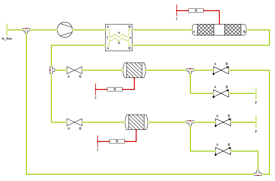
Co-electrolysis is an electrochemical process for the production of synthesis gas - a mixture of hydrogen and carbon monoxide, which can be used to produce methane or methanol. Water vapour and CO2 are used as starting materials, which are split into H2, CO and O2 using electric current.
An optimum ratio of H2 to CO is often required for further processing of the synthesis gas. For example, the optimum H2/CO ratio for methanation is a value of 3.
In co-electrolysis, the H2/CO value is determined by process parameters such as temperature, current density, or educt gas composition. The latter will be analysed in more detail in this example.
Simulation
In this example, a solid oxide electrolyser for the production of synthesis gas is simulated. At the beginning of the simulation, a gas mixture of water vapour and CO2 is introduced in a ratio of 1:1. Later in the simulation, the proportion of water vapour in the reactant mixture is slowly increased.

Result
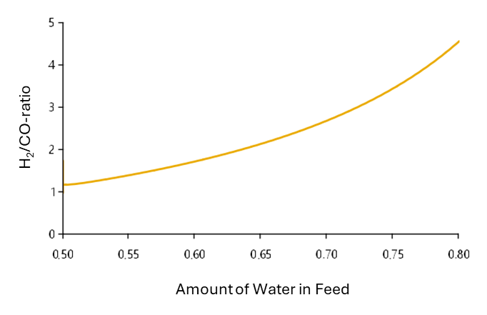
In the case of an equimolar reactant composition, the present process parameters result in an H2/CO ratio of 1.2. Increasing the water content also increases the proportion of hydrogen in the synthesis gas. The optimum ratio of 3 for methanation is achieved in this simulation with a water content of around 72 %.
Co-Electrolysis: Optimal Reactant Composition
Investigation of the influence of the educt mixture on the composition of the synthesis gas
Read example >
System
The speed of the methanation reaction is influenced by various factors, such as temperature, pressure and composition of the mass flow entering the reactor. During operation, these variables change dynamically for various reasons and thus influence the performance of the methanation.
In order to reduce energy costs, it often makes sense to integrate the reactor into a complex energy system and to utilize the heat from the exothermic reaction in other sub-processes. To do this, it is important to understand how the reactor behaves when the temperature changes to design the system correctly.

Simulation
In this example, the pressure in the reactor and the feed composition are kept constant. The reactor and feed temperatures are continuously increased from 280 to 350 °C at the same time. This allows the influence of the reactor temperature on methanation to be analysed without disruptive effects.
Result

As the reactor temperature rises, the heat flow generated by the reaction increases. This is mainly due to the increased reaction rate. When designing a heat recovery system, it must therefore be considered that more heat must be dissipated when the reactor temperature increases!
Power-to-Methane: Integration of the Reactor into a Heat Integration System
Temperature-dependent analysis of a power-to-methane process for incorporation into a heat integration system
Read example >
System
The energy requirement for alkaline electrolysis is significantly influenced by the electrical voltage in the cells. The lower the cell voltage at an applied current density, the more efficient the electrolysis process is.
During operation, however, ohmic resistances — triggered by the current flow through the cell components — cause the cell voltage to increase. This results in power losses.
One measure to reduce ohmic losses is the zero-gap arrangement. In this cell design, the two porous electrodes lie directly on the separator so that the electric current no longer has to flow through the two electrolyte channels:

Simulation
To illustrate the increase in efficiency due to the zero-gap arrangement, an electrolysis stack with conventional and then with zero-gap cells is simulated in this example. The applied current density is increased during the simulation and the resulting cell voltage is recorded. The result is the polarization curve - a correlation between the current density and the cell voltage.
Result
As the current density increases, the voltage in the cells also increases. In contrast to conventional cells the curve in the zero-gap alternative rises much flatter. For electrolysis operation, this means that a lower voltage is present in the cells once the desired current density has been set. Ultimately, the lower voltage in the zero-gap cells leads to a reduced energy requirement.


Zero-Gap Assembly in Alkaline Electrolysis
Increased efficiency through compact cell design in alkaline electrolysis
Read example >
System
During water electrolysis waste heat is generated in the PEM stack. This heat must be dissipated to enable efficient operation of the electrolyser. For many stacks, the manufacturer also specifies a maximum temperature rise ∆Tmax between the incoming and outgoing reactant flow. If ∆Tmax is exceeded, the lifetime of the stack is reduced and therefore also the economic efficiency of the system.
One way to influence this temperature increase is to adjust the incoming mass flow so that ∆Tmax is not exceeded. However, to keep the pump output low, it makes sense to keep this mass flow as low as possible. The optimum temperature rise is therefore ∆Tmax. A suitable control strategy also helps to maintain this value dynamically.

Simulation
A 2 MW electrolyser is considered, to which a wind turbine of the same size is coupled. Depending on the wind strength, the electrolyser is utilized to a greater or lesser extent and the temperature rise is controlled to ∆Tmax as described above. Two different control strategies are simulated and compared:
- Variant 1: Measurement of the temperatures at the inlet and outlet of the stack, subsequent PI control of the mass flow rate
- Variant 2: Model Predictive Control of the mass flow based on the incoming electrical current
Result

The graph shows that a significant improvement in the control accuracy can be achieved through model predictive control. The temperature overshoot is significantly lower than with the 1st variant and a stable state is reached more quickly. This example was presented by TLK Energy and Neuman and Esser at the International Modelica Conference 2023.
PEM Electrolyzer: Optimal Stack Cooling
Optimal Control of Cooling for a PEM Electrolyzer in Dynamic Operation
Read example >

Sprechen Sie mit uns über Ihr Projekt

Ihre Ansprechpartnerin
Hanna Leder (Account Manager) ist Ihre Ansprechpartnerin für den ersten Austausch. Sie klärt mit Ihnen die nächsten Schritte und bringt Sie mit dem passenden Experten zusammen.
© 2026 TLK Energy. All rights reserved.